Flow Network: Concept
Define and explain the capacity property and the conservation property of a flow network.
- The definition may use a formula for a given flow network , where is the set of nodes, is the set of edges, is the source node, is the sink node, is a function that returns the flow assigned to an edge , and is a function that returns the capacity of an edge .
- The explanation should state the intuitive meaning of the constraint specified by the property.
State the key idea that enables the Ford-Fulkerson algorithm to remedy a wrong choice of augmenting flow in the flow network toward eventually finding a maximum flow.
Given a cut (A, B) in a flow network, (i) write the definition of the cut’s capacity and write how the capacity is calculated, and (ii) write the conditions required of edges crossing the cut if the cut is a minimum cut. Give your answers as intuitive statements without using equations.
Capacity / Conservation Properties
We know we can define the capacity property for all edges as satisfying the flow:
This means that the capacity constraint ensures that flow on any given edge will not exceed a maximum capacity of said edge, and cannot be negative. It represents the absolute maximum threshhold like a constrained fluid pipe, where it can only handle so much per unit time.
We can define the conservation property for all nodes :
we can define this more formally by replacing into/out of with their respective ordered pairs in set :
By the conservation property we can state that at every intermediate node, the total flow of said node must equal the total flow leaving the node. Flow cannot be created nor destroyed at intermediate nodes and thus what comes in must go out.
Backward Edges for Ford Fulkerson
The big idea is that we can use the function of residual graphs that have backward edges as a method to repair wrong choices made.
When our algorithm makes a suboptimal flow decision along an edge, it can later be undone or reduced by sending flow backward along that edge. This can be defined by:
If we send units along edge , our residual graph now includes that backward edge with residual capacity . Over the next few iterations, the algorithm can then find path improvements that use this backward ege, reducing the flow on the first edge.
In essence, the backward edges give the algorithm the flexibility to adjust earlier decisions without having to start over from scratch, similar to the idea of redirecting flow from the previous suboptimal path.
Cuts for Flow Networks
We define the cut capacity for a given cut where :
This cut is the sum of the capacities of all edges that go from the source side to the sink side . Edges going in the reverse direction (from ) are not counted in the capacity. We can then do the calculation by summing up for all edges where and .
This cut capacity represents the max total flow that could be achieved from crossing source to sink for this given partition.
For the minimum cut condition, we assume a cut is a minimum cut if and only if all forward edges are saturated(meaning every edge goin from to has a flow equal to its full capacity, no unused capacity) and all backward edges carry zero flow(meaning each edge going from to carries no flow at all).
A minimum cut is represented as a bottleneck in this network being pushed to its maximum limits. All paths through the cut are completely utilized in the forward directions, and there is zero flow going backwards through the cut (indication inneficiency). This cut has the smallest capacity among all possible cuts, and by the max-flow min-cut theorem, the value of the maximum flow equals this minimum cut capacity.
Network Flow Ford-Fulkerson Algorithm Tracing
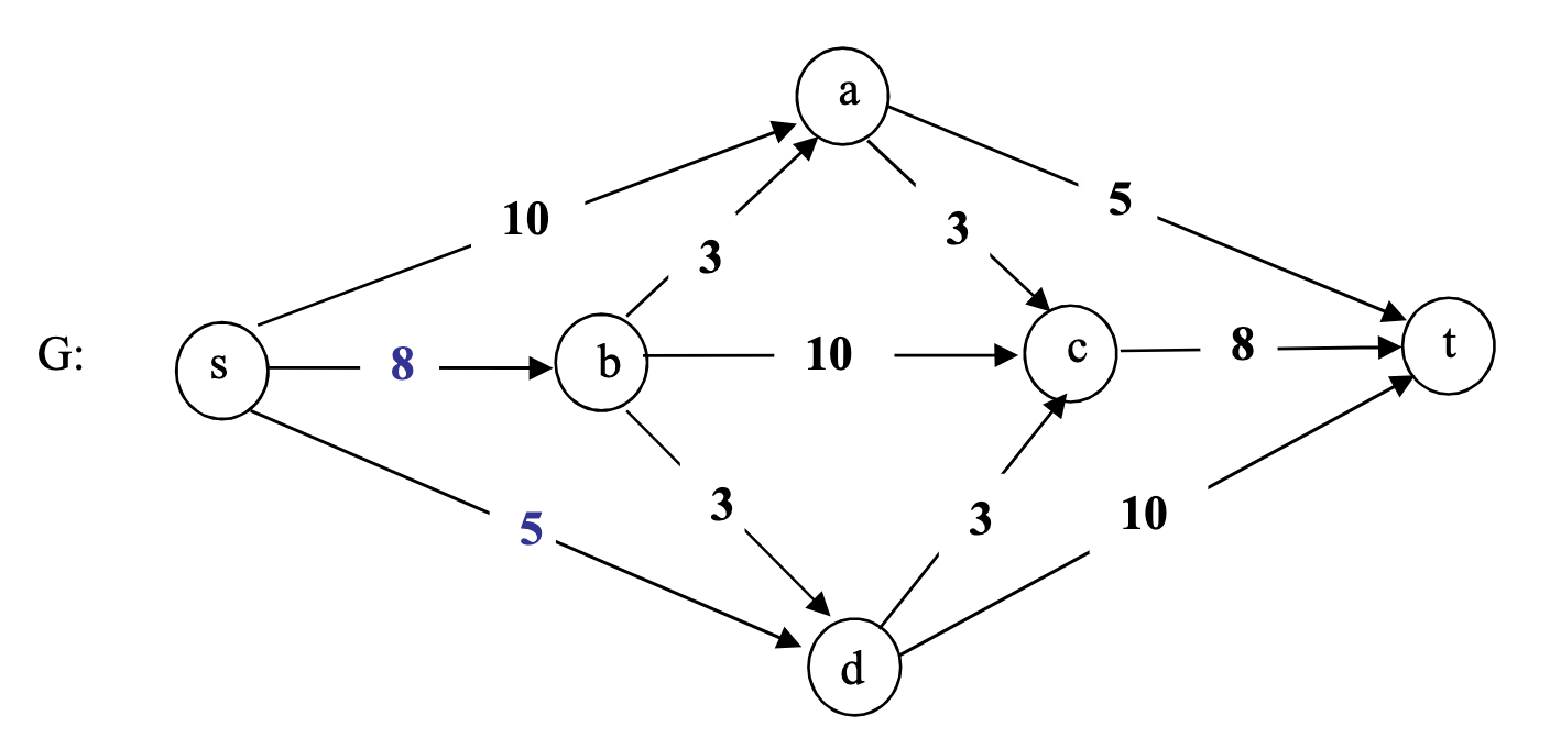
Consider the flow network shown below (reformatted from Textbook Figure 7.26 in page 415). Run the Ford-Fulkerson algorithm to find the maximum flow and a minimum cut. Show the results of running the algorithm as specified below.
- Write the list of pairs of an augmenting path found (e.g., ) and the flow amount augmented during the algorithm execution. For this exercise, choose augmenting paths in a non-increasing order of the bottleneck flow amount, that is, a path with the largest bottleneck first.
- Write the final (i.e., maximum) flow value on every edge in the flow network and also write the calculated max flow value and the min cut capacity. Additionally, draw a line showing the minimum cut across the flow network (see the lecture slide for an example).
- Draw the final residual graph with all the final residual capacities – both forward and backward – shown on the edges. Additionally, draw a line surrounding the nodes reached from the source node s at the end of the algorithm execution (see the demo slide for an example).
Augmenting Paths
Running Ford-Fulkerson with paths selected by largest bottleneck flow:
Yielding that no more augmenting paths exist.
Maximum Flow and Minimum Cut
Final flow values:
Max flow value: 21
We define the minimum cut with the following parameters:
Edges crossing the cut (): : capacity 8, : capacity 5, : capacity 3, : capacity 5
Minimum Cut Capacity:
Flow Network with Minimum Cut: see figure 2
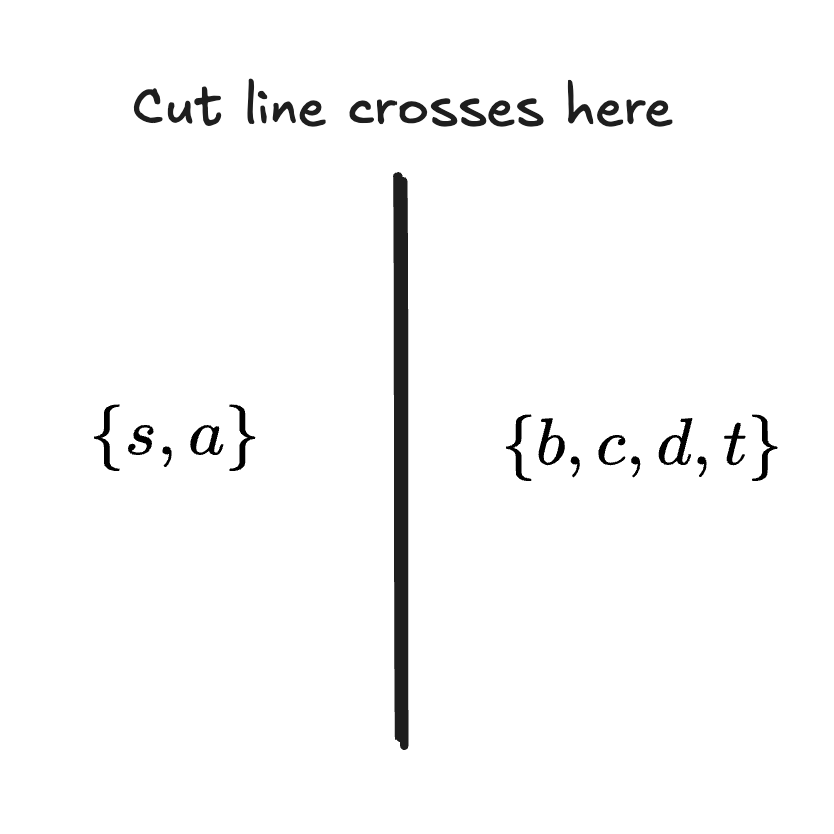
The cut separates nodes from .
Final Residual Graph
The residual graph shows remaining forward capacities and backward capacities: see figure 3, sorry for poor quality sketch as I was having difficulties wtih my conventional approach.
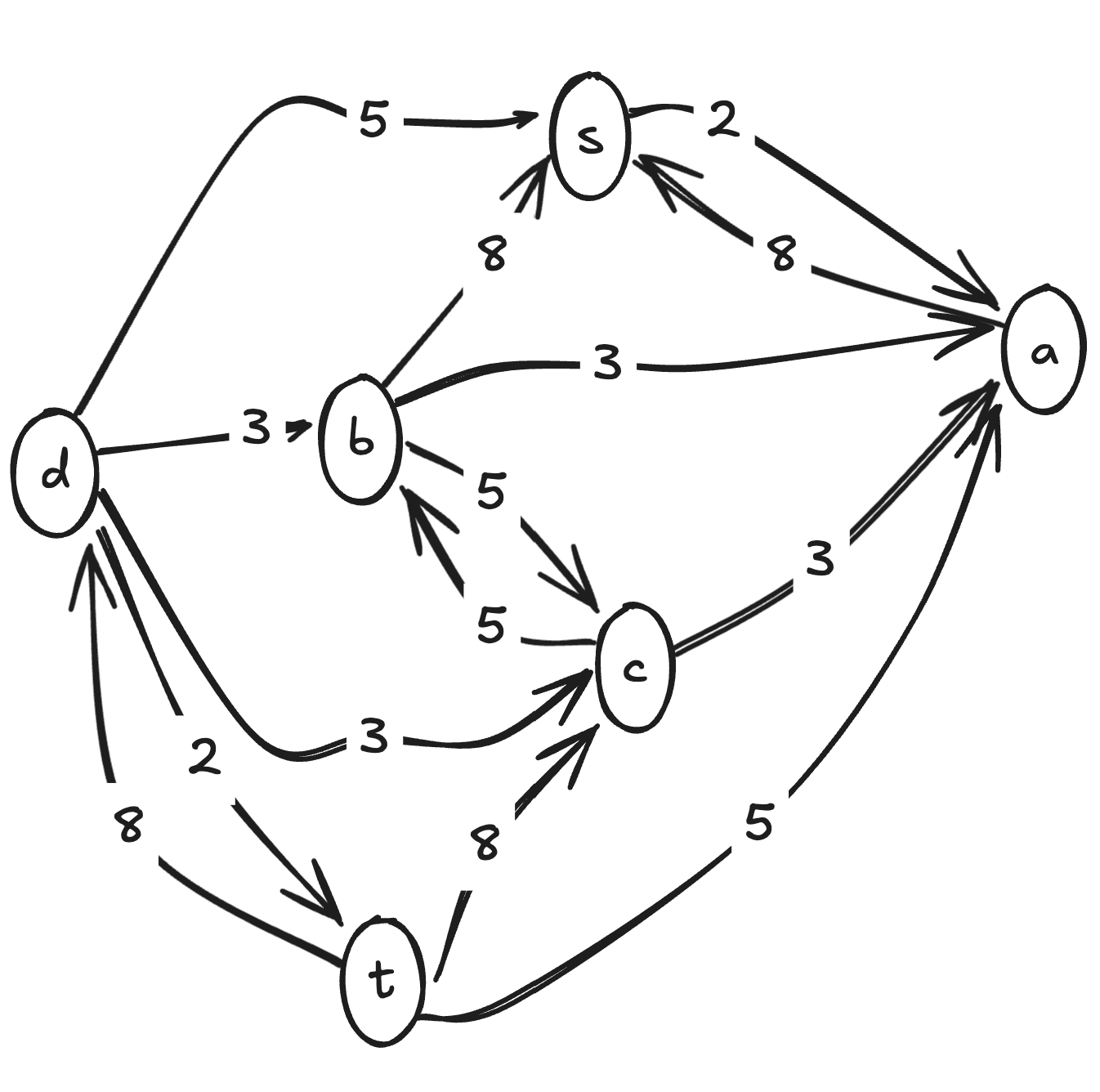
Residual Capacities (Forward/Backward):
- Forward residuals: : 2, : 3, : 5, : 3, : 2
- Backward residuals (can reduce flow): : 8, : 8, : 5, : 3, : 5, : 3, : 5, : 8, : 8
Nodes Reachable from S:
In the final residual graph, starting from we can reach: (starting node), (via with residual capacity 2)
No other notdes can be reached from , ass all outgoing edges are thus saturated. Meaning our set of reachable nodes is:
This confirms our minimum cut: the cut separates reachable nodes from unreachable nodes .